")
")
")


Manufacture of hydraulic control and power units
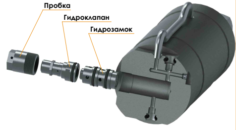
Pressure-release valve HKP 100 /ГКП 100/
Pressure-release valve HKP 100 is designed for protection from mining pressure of hydraulic props and hydraulic jacks of powered supports, as well as other mining machines.
Comparative table of main parameters for pressure-release valves HKP 100 and KPS /КПС/
(serial production since 2003)
|
Technical characteristics |
Value |
|
|
HKP100 |
KPS |
|
|
1. Maximum throughput capacity , l/min |
100±10 |
9±1 |
|
2. Set point pressure , MPa : |
|
|
|
- nominal |
39 |
39 |
|
- full |
50 |
50 |
|
3. Dimensional specifications , mm, no more than: |
|
|
|
- length |
89 |
92 |
|
- diameter |
38 |
38 |
|
4. Mass , kg, no more than |
0,45 |
0,5 |
Predominant features of pressure-release valve HKP 100 as compared to KPS:
1. The capacity is increased by 10 times, which provides protection of hydraulic power units and the structure of the powered support in case of the sudden top subsidence and roof fall.
2. The resource and reliability of operation are increased, which leads to the reduction of repair costs.
3. The number of precision components is reduced by 15%, which leads to a reduction in the cost of the valve.
This valve is interchangeable with the KPS valve. The design of the KPS valve ensures simple assembly and easy extraction from the hydraulic block.
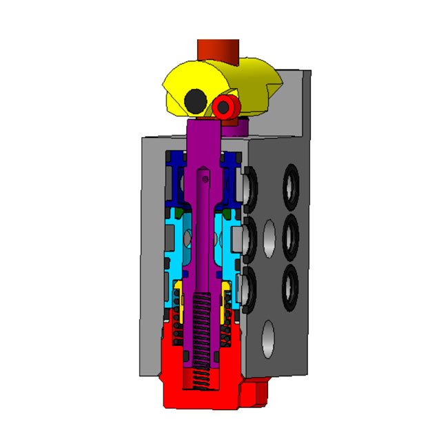
Locking valve HUK12 /ГУК 12/
Locking valve HUK 12 is designed for the hydraulic system of powered supports and other mining machines in order to increase the flow of the power fluid in one direction and to lock it in the opposite direction until the hydraulic control impulse is applied, opening the locking valve for the flow in both directions.
Comparative table of main parameters for HUK12 и KHU-3U /КГУ-3У/ (serial production since 1981)
| Name of the parameter and size | Value | |
| HUK12 | KHU-3U | |
| 1 Internal diameter, no less than, mm | 12 | 8 |
| 2 Nominal preassure, MPa | 50 | 50 |
| 3 Nominal flow rate, l/min | 150 | 100 |
| 4 Full flow rate, l/min | 200 | 150 |
| 5 Pressure fall at the expense of 100 l/min, no more than, MPa | 2,8 | 4 |
| 6 Opening pressure of the locking vave, MPa, no more than | 6,7 | 8 |
| 7 Drain pressure, MPa, no more than | 5 | 5 |
| 8 Dimensions, mm, no more: | ||
| - length | 66 | 73 |
| - diameter | 38 | 38 |
| 9 Mass, kg, no more than | 0,36 | 0,36 |
Predominant features of the locking valve HUK12 as compared to KHU-3U:
1. The throughput capacity is rased by 1.5 times that increases the speed of movement of the powered support by the combine and valve of the conveyor line, thereafter the amount of coal produced is increased.
2. The resource and reliability of operation are increased, which leads to the reduction of repair costs.
3. The number of precision components is reduced by 20%, which leads to a reduction in the cost of the valve.
4. This valve is interchangeable with the KHU valve. The design of the HUK valve ensures simple assembly and easy extraction from the hydraulic block, that simplifies and speeds up the work.
Directional control hydraulic valve HRP12
Directional control hydraulic valve HRP12 is designed for local (manual) control of working bodies (hydraulic props, hydraulic jacks, hydraulic expansion toolholders) of powered supports and other mining machines.
Comparative table of main parameters for directional control hydraulic valves HRP12 and RSD-05
/РСД-05/ (serial production since 1998)
|
||||||||||||||||||||||||||||||||||||||||||
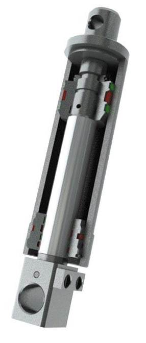
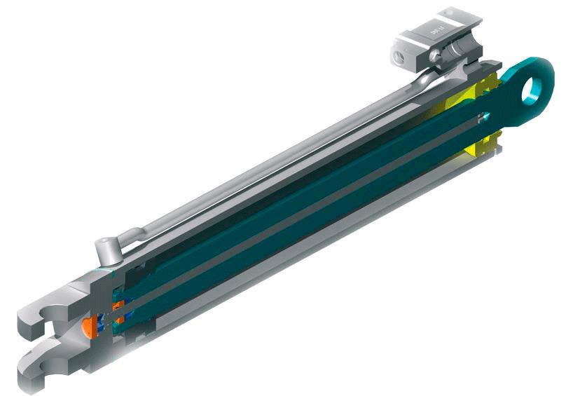
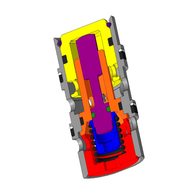
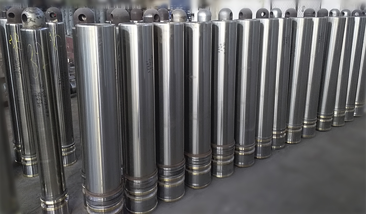
HYDRAULIC JACKS
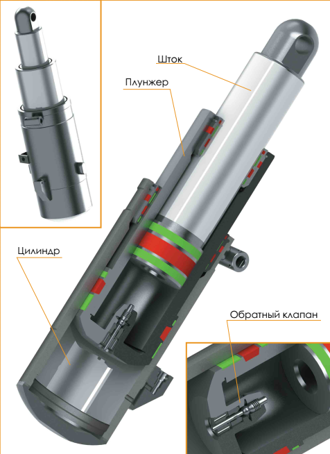
Hydraulic jacks are part of the powered support and are designed for pulling out of shields of the powered support during adjustment of position of the sections and their folding; perform the functions of moving the sections, basic elements, conveyor, moving-out or moving elements of the overlap, etc. Hydraulic jacks carry out movement, position regulation and fixation of the powered supports, working in the underground conditions without restrictions in mining and geological field.
By the nature of the work, hydraulic jacks have single-sided or double-sided action. By the nature of the design - single and double extention. Hydraulic jack with single extension are most widely used. The of a hydraulic jack is equal to the width of the extracting machine or a multiple of it.
Hydraulic jacks are made of qualitative constructional carbon steels of marks: Steel 45, Steel 35 of the National State Standard /ГОСТ/ 1050-88; constructional alloyed steels of marks: 30KHHSA /30ХГСА/ of the National State Standard 4543-71. Surfacing is made by surfacing wire of the mark Boehler AWSER 307. For assembly and welding operations MR-3 Monolith /МР-3 Монолит/ electrodes and ATOM 307 Si welding wire are used. Welding is performed in shielding gas environment. PF115 enamel of the National State Standard 6465-76 is used for lacquer coating. The hydraulic fluid for hydraulic jacks is Emulsol E2-ED-3 /Е2-ЕД-3/.
The main indicators and characteristics of hydraulic jacks meet the requirements of the National State Standard R 55157-2012, the National State Standard 151850, the National State Standard 16514.
|
Main features of the hydraulic jack according to TS U /ТУ У/ 24.3-33717202-003:2018* |
|||||
|
Name |
Value |
The conveyor's pushing force , kN |
Section pull up force , kN |
Move, mm |
Mass, kg |
|
1KD90.14.02.000 |
Hydraulic advancing ram |
180 |
304 |
859 |
80 |
|
1KD90.28.02.000 |
Hydraulic jack |
170 |
304 |
905 |
103,7 |
|
1KD90.46.02.000 |
Hydraulic jack |
170 |
304 |
905 |
77 |
|
1KD90.46.00.080 |
Hydraulic jack |
90,4 |
50,2 |
100 |
12,1 |
|
1KD90.54.02.000 |
Hydraulic jack |
170 |
304 |
735 |
94,5 |
|
1KD90.62.02.000 |
Hydraulic jack |
170 |
304 |
735 |
69 |
|
1KD90.62.02.000 |
Hydraulic jack |
170 |
304 |
860 |
73 |
|
1KD80.13.02.000 |
Hydraulic jack |
170 |
304 |
860 |
73 |
|
2KD90.14.02.000 |
Hydraulic jack |
230 |
39,2 |
510 |
81,7 |
|
2KD90.46.02.000 |
Hydraulic jack |
170 |
304 |
704 |
64 |
|
3KD90.12.00.080 |
Hydraulic jack for side shields |
90,4 |
50,2 |
100 |
12 |
|
3KD90.13.00.080 |
Hydraulic jack for side shields |
90,4 |
50,2 |
100 |
12,5 |
|
3KD90.14.02.000 |
Hydraulic jack |
170 |
304 |
690 |
62 |
|
3KD90.16.02.000 |
Hydraulic jack advancing ram |
230 |
392 |
690 |
98,8 |
|
3KD90.13.02.000 |
Hydraulic jack |
230 |
392 |
690 |
98,8 |
|
3KD90.46.02.000 |
Hydraulic jack |
230 |
392 |
704 |
107 |
|
3KD90.58.02.000 |
Hydraulic jack |
230 |
392 |
878 |
118 |
|
3KD90.58.00.100 |
Hydraulic jack |
180 |
304 |
382 |
46,3 |
|
3KD90.59.00.250 |
Hydraulic jack |
230 |
392 |
815 |
118 |
|
3KD90.50.02.000 |
Hydraulic jack |
230 |
392 |
690 |
98,8 |
|
3KD90.91.02.000 |
Hydraulic jack |
230 |
392 |
690 |
95,8 |
|
1М87Е.23.43.000 |
Hydraulic jack |
266 |
158 |
680 |
64,6 |
|
1KD90Т.11.02.000 |
Hydraulic jack |
230 |
392 |
916 |
111 |
|
1KD90Т.12.02.000 |
Hydraulic jack |
230 |
392 |
745 |
98 |
|
2KD90Т.18.02.000 |
Hydraulic jack |
230 |
392 |
745 |
103,7 |
|
2KD90Т.22.02.000 |
Hydraulic jack |
230 |
392 |
410 |
69 |
|
2KD90Т.23.02.000 |
Hydraulic jack |
230 |
392 |
745 |
103,7 |
|
2KD90Т.03.000П |
Hydraulic jack advancing ram |
230 |
392 |
745 |
103,7 |
|
4KD90Т.16.02.000 |
Hydraulic jack advancing ram |
230 |
392 |
690 |
103,7 |
|
DМ11.02.000 |
Hydraulic jack |
180 |
304 |
690 |
58 |
|
DМ11.04.000 |
Hydraulic jack |
15,3 |
20,3 |
98 |
14,7 |
|
DМ11.08.000 |
Hydraulic jack |
90,5 |
39,6 |
105 |
9,66 |
|
DМ11.16.000 |
Hydraulic jack |
392 |
230 |
205 |
74,3 |
|
DМ14.04.000 |
Hydraulic jack lifting jack |
15,3 |
20,3 |
115 |
14,7 |
|
DМ14.08.000 |
Hydraulic jack |
39,6 |
90,5 |
105 |
12,8 |
|
DМ16.02.000 |
Hydraulic jack advancing ram |
180 |
304 |
1103 |
59,7 |
|
DМ24.08.000 |
Hydraulic jack stabilizer jack |
180 |
304 |
1103 |
59,7 |
|
DМ44.02.000 |
Hydraulic jack |
180 |
304 |
690 |
59,7 |
|
1KDD.14.02.000 |
Hydraulic jack |
90,4 |
50,2 |
100 |
12 |
|
1KDD.24.08.000 |
Hydraulic jack |
392 |
230 |
205 |
72 |
|
1KDD.24.02.000 |
Hydraulic jack advancing ram |
231 |
392 |
690 |
98,6 |
|
1KDD.23.08.000 |
Hydraulic jack |
392 |
230 |
205 |
72 |
|
1KDD.14.08.000 |
Hydraulic jack |
392 |
230 |
205 |
74,3 |
|
2KDD.17.08.000 |
Hydraulic jack stabilizer jack |
643 |
392 |
334 |
95 |
|
2KDD.31.11.000 |
Hydraulic jack of the console |
113 |
204 |
593 |
42,7 |
|
2KDD.25.08.000 |
Hydraulic jack |
643 |
392 |
334 |
95 |
|
2KDD.32.08.000 |
Hydraulic jack |
643 |
392 |
334 |
95 |
*32 Operating pressure, MPa
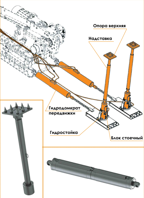
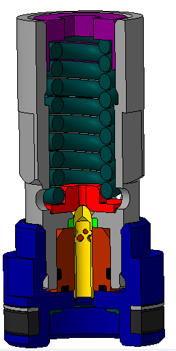
Hydraulic props
Hydraulic jacks are made of qualitative constructional carbon steels of marks: Steel 45, Steel 35 of the National State Standard /ГОСТ/ 1050-88; constructional alloyed steels of marks: 30KHHSA /30ХГСА/ of the National State Standard 4543-71. Surfacing is made by surfacing wire of the mark Boehler AWSER 307. For assembly and welding operations MR-3 Monolith /МР-3 Монолит/ electrodes and ATOM 307 Si welding wire are used. Welding is performed in shielding gas environment.
Test methods
|
Main features of the hydraulic props* to TS U /ТУ У/ 24.3-33717202-003:2018* |
|
||||||||
|
Name |
Exten-tion , mm |
Height, mm |
Load-lifting capacity, kN |
Ø of the head end, mm |
Ø of the plunger cavity, mm |
Pressure in the plunger cavity of the cylinder, mPa |
Forced lowering effort , kN |
Mass, kg |
|
|
1KD80.14.01.000 |
594 |
525 |
820 |
Ø110 f9 |
Ø160 f9 |
82 |
97 |
114 |
|
|
1KD90.14.01.000 |
594 |
525 |
820 |
Ø110 f9 |
Ø160 f9 |
82 |
97 |
114 |
|
|
1KD90.12.01.000 |
550 |
573 |
820 |
Ø110 f9 |
Ø160 f9 |
82 |
97 |
107 |
|
|
1KD90.13.01.000 |
590 |
593 |
820 |
Ø110 f9 |
Ø160 f9 |
82 |
97 |
105,6 |
|
|
1KD90.15.01.000 |
734 |
658 |
820 |
Ø110 f9 |
Ø160 f9 |
82 |
97 |
138 |
|
|
1KD90.18.01.000 |
734 |
658 |
820 |
Ø110 f9 |
Ø160 f9 |
82 |
97 |
138 |
|
|
1KD90.27.01.000 |
590 |
594 |
820 |
Ø110 f9 |
Ø160 f9 |
82 |
97 |
104,8 |
|
|
1KD90.28.01.000 |
590 |
593 |
820 |
Ø110 f9 |
Ø160 f9 |
82 |
97 |
110 |
|
|
1KD90.60.01.000 |
653 |
621 |
820 |
Ø110 f9 |
Ø160 f9 |
82 |
97 |
110 |
|
|
1KD90.62.01.000 |
550 |
569 |
820 |
Ø110 f9 |
Ø160 f9 |
82 |
97 |
118,7 |
|
|
1KD90.74.01.000 |
653 |
624 |
820 |
Ø110 f9 |
Ø160 f9 |
82 |
97 |
112 |
|
|
1KD90.78.01.000 |
820 |
678 |
1290 |
Ø110 f9 |
Ø160 f9 |
69 |
100 |
123 |
|
|
2KD90.16.01.000 |
590 |
687 |
820 |
Ø110 f9 |
Ø160 f9 |
82 |
97 |
129 |
|
|
2KD90.62.01.000 |
744 |
669 |
820 |
Ø110 f9 |
Ø160 f9 |
82 |
97 |
120 |
|
|
2KD90.64.01.000 |
848 |
721 |
820 |
Ø110 f9 |
Ø160 f9 |
82 |
97 |
132 |
|
|
2KD90.78.01.000 |
820 |
687 |
1290 |
Ø110 f9 |
Ø160 f9 |
69 |
100 |
129 |
|
|
2KD90.92.01.000 |
666 |
644 |
820 |
Ø110 f9 |
Ø160 f9 |
82 |
97 |
109 |
|
|
3KD90.16.01.000 |
594 |
963 |
820 |
Ø110 f9 |
Ø160 f9 |
82 |
97 |
180 |
|
|
3KD90.50.01.000 |
1030 |
963 |
820 |
Ø110 f9 |
Ø160 f9 |
82 |
97 |
177 |
|
|
3KD90.66.01.000 |
1014 |
943 |
820 |
Ø110 f9 |
Ø160 f9 |
82 |
97 |
172 |
|
|
3KD90.68.01.000 |
1130 |
1113 |
820 |
Ø110 f9 |
Ø160 f9 |
82 |
97 |
185 |
|
|
3KD90.78.01.000 |
820 |
963 |
1290 |
Ø110 f9 |
Ø160 f9 |
69 |
100 |
180 |
|
|
KD90Т.22.01.000 |
1290 |
931 |
1290 |
Ø110 f9 |
Ø160 f9 |
69 |
100 |
225 |
|
|
1KD90Т.11.01.000 |
511 |
588 |
1290 |
Ø110 f9 |
Ø160 f9 |
69 |
100 |
160 |
|
|
1KD90Т.12.01.000 |
577 |
621 |
1290 |
Ø110 f9 |
Ø160 f9 |
69 |
100 |
174 |
|
|
1KD90Т.70.01.000 |
512 |
591 |
1290 |
Ø110 f9 |
Ø160 f9 |
69 |
100 |
155 |
|
|
2KD90Т.18.01.000 |
680 |
|
1290 |
Ø110 f9 |
Ø160 f9 |
69 |
100 |
177 |
|
|
3KD90Т.22.01.000 |
680 |
|
1290 |
Ø110 f9 |
Ø160 f9 |
69 |
100 |
225 |
|
|
3KD90Т.32.01.000 |
818 |
|
1290 |
Ø110 f9 |
Ø160 f9 |
69 |
100 |
222 |
|
|
3KD90Т.46.01.000 |
680 |
|
1290 |
Ø110 f9 |
Ø160 f9 |
69 |
100 |
260 |
|
|
3KD90T.68.01.000 |
1077 |
931 |
820 |
Ø110 f9 |
Ø160 f9 |
82 |
97 |
185 |
|
|
4KD90Т.68.01.000 |
1130 |
|
1290 |
Ø110 f9 |
Ø160 f9 |
69 |
100 |
320 |
|
|
DМ.16.01.000 |
680 |
|
1530 |
Ø110 f9 |
Ø160 f9 |
84 |
233 |
236 |
|
|
DМ18.01.000 |
680 |
|
1530 |
Ø110 f9 |
Ø160 f9 |
84 |
233 |
234 |
|
|
DМ.19.01.000 |
680 |
|
1530 |
Ø110 f9 |
Ø160 f9 |
84 |
233 |
234 |
|
|
DМ.41.01.000 |
810 |
|
1530 |
Ø110 f9 |
Ø160 f9 |
84 |
233 |
267,6 |
|
|
1KDD.14.01.000 |
735 |
|
1527 |
Ø110 f9 |
Ø160 f9 |
84 |
211 |
256,6 |
|
|
1KDD.17/36.01.000 |
735 |
|
1530 |
Ø110 f9 |
Ø160 f9 |
84 |
211 |
250 |
|
|
2KDD.27.01.000 |
735 |
|
1530 |
Ø110 f9 |
Ø160 f9 |
84 |
211 |
348 |
|
|
2KDD.31.01.000 |
735 |
|
1530 |
Ø110 f9 |
Ø160 f9 |
84 |
211 |
360 |
|
|
2KDD.35.01.000 |
735 |
|
1530 |
Ø110 f9 |
Ø160 f9 |
84 |
211 |
345 |
|
|
2KDD.60.01.000 |
735 |
|
1530 |
Ø110 f9 |
Ø160 f9 |
84 |
233 |
296 |
|
|
1KDDL.17.01.000 |
755 |
|
1530 |
Ø110 f9 |
Ø160 f9 |
84 |
211 |
250 |
|
* Pressure in the head end of the cylinder 39 mPa;
Ø of the head end, mm Ø110 f9;
Ø plunger cavity, mm Ø160 f9.